# 目录
- 简介
- 配件清单
- 熟悉相机
- 熟悉主机
- 可选配件
- 设置向导:分步指引
- 1 放置标记点
- 2 建图
- 3 地图校准
- 4 定义虚拟影棚
- 5 安装 RedSpy 相机
- 6 设置 IP 地址
- 7 精细调校
- RedSpy 用户界面总览
- 主屏幕
- 网络
- 相对主相机的偏移
- 建图
- 滑块
- 镜头校准
- 配置文件
- 许可证
- 诊断
- 运行 RedSpy 设置向导
- stYpe 配套产品
# 简介
RedSpy 是一套光学相机追踪解决方案,在提供极高精度的同时,也能从容应对实际制作现场常见的非理想工作环境。在影棚四周布置回反射标记点(retroreflective marker),由 RedSpy 相机捕捉它们的位置;图像信息再辅以 IMU(惯性测量单元)数据,并交由经过精细调校的智能算法解算,从而提供最高水准的相机追踪质量。这让 RedSpy 即便面对最复杂的相机运动也能应付自如——从摇臂、斯坦尼康到手持设备都适用,丝毫不会束缚你的创作自由。
用户界面内置了一个分步安装向导,引导用户完成系统的初次设置。每个环节都会给出相应的操作提示,只要照着做,就足以获得可靠的相机追踪表现。即便如此,我们仍额外提供这份手册,帮助你更深入地理解 RedSpy 的内部原理。首次安装时,使用向导能让设置过程更顺畅——即使对相机追踪的各种细节早已熟悉的影棚也是如此。如果系统已经设置完毕,请参阅"用户界面总览"一节,了解各个界面标签页的概况。
# 配件清单
一套完整的 RS 套件出厂时包含下列组件。你拿到的套件,配件可能与这里所列略有出入。
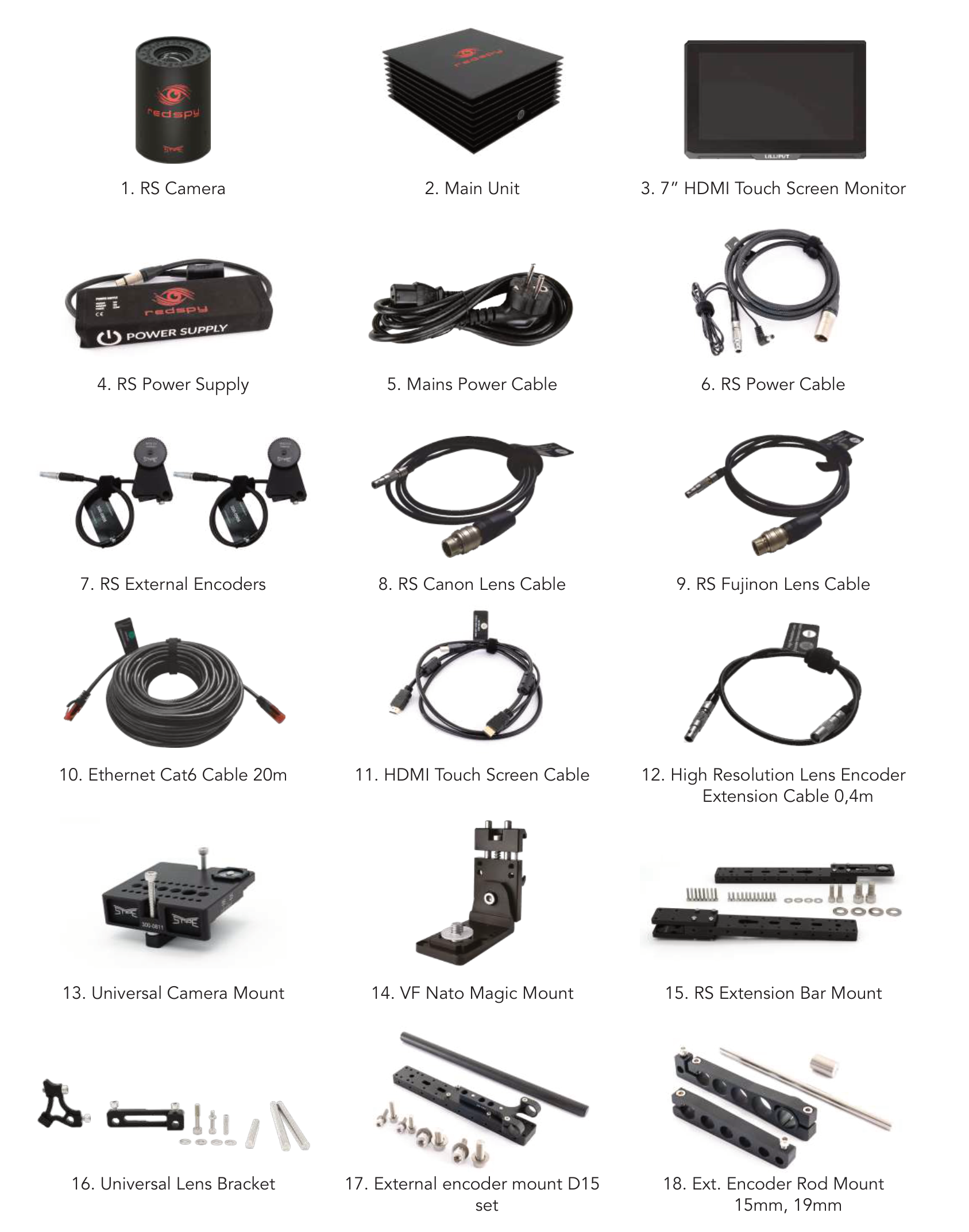
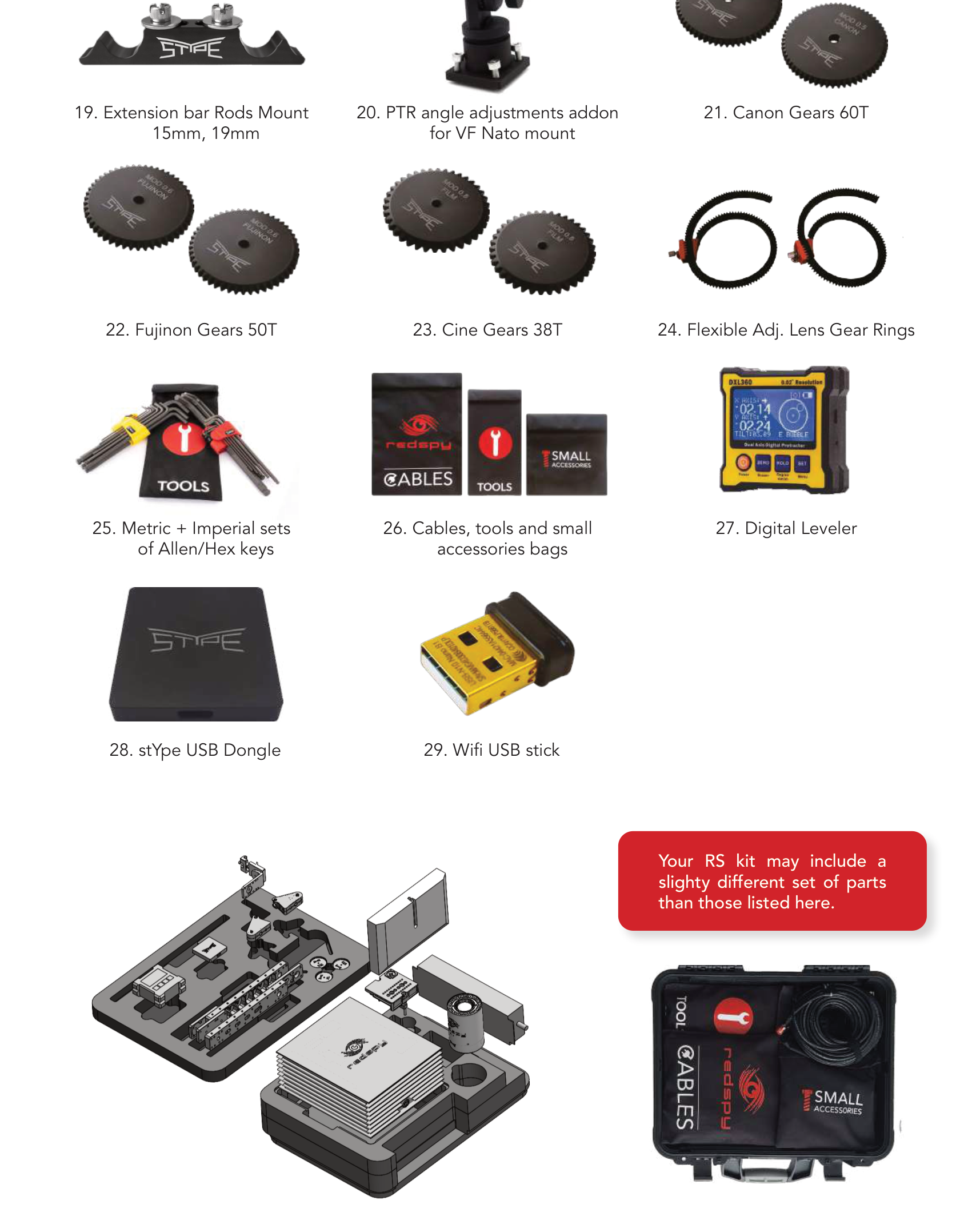
1. RS 相机
2. 主机(Main Unit)
3. 7 英寸 HDMI 触摸屏显示器
4. RS 电源
5. 市电电源线
6. RS 电源线
7. RS 外置编码器
8. RS 佳能镜头线
9. RS 富士能镜头线
10. 20 米六类网线(Cat6)
11. HDMI 触摸屏连接线
12. 高分辨率镜头编码器延长线 0.4 米
13. 通用相机支架
14. VF Nato 快装座
15. RS 延长杆支架
16. 通用镜头托架
17. D15 外置编码器支架套件
18. 外置编码器杆夹(15mm、19mm)
19. 延长杆杆夹(15mm、19mm)
20. VF Nato 座的 PTR 角度调节配件
21. 佳能齿轮 60T
22. 富士能齿轮 50T
23. 电影镜头齿轮 38T
24. 柔性可调镜头齿圈
25. 公制 + 英制内六角扳手套装
26. 线缆、工具及小配件收纳袋
27. 数字水平仪
28. stYpe USB 加密狗
29. Wifi USB 接收器
# 熟悉相机
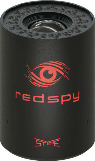
- **RS 标识** — 相机正面的 RedSpy logo 与版本号。
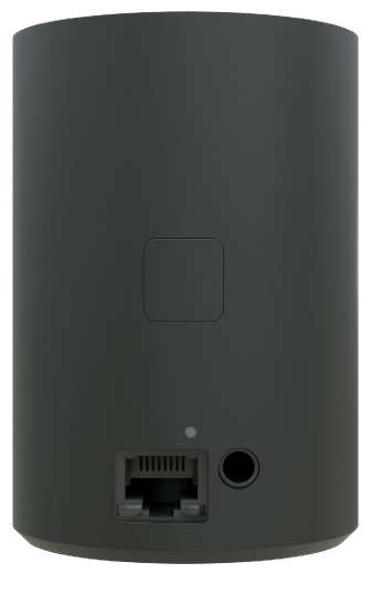
- **指示灯(Indicator LED)** — 每次按键都会点亮。系统首次启动时还会亮起蓝色,确认相机已正常通电。
- **CAM 端口** — RJ45 端口,连接 RedSpy 相机与系统主机,负责二者通信,并通过 PoE 为相机供电。
- **Action 按钮** — 情景式按钮,在 RedSpy 界面的不同位置执行不同功能。
- **镜头编码器端口** — 外置编码器套件或富士能/佳能镜头线接在这里,向系统提供镜头位置数据。
> **合适的 PoE 标准与线缆**
>
> RedSpy 相机不一定要直接插到主机上——它支持符合 802.3at(PoE+)和 802.3bt(PoE++)标准的任意 PSE(供电设备)。这类 PSE 设备通常是网络交换机或 PoE 注入器。套件随附一根 20 米长的六类(Cat 6)UTP 网线;不过若 RedSpy 相机与主机的距离更远,建议改用七类(Cat 7)线缆。
# 熟悉主机
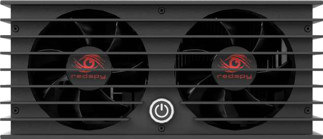
- **电源(Power)** — 位于主机正面的开关机按钮。
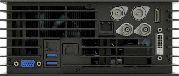
1. **EXT LAN** — RJ45 端口,把追踪数据直接或经由网络交换机送往渲染工作站。
2. **USB** — 两个 USB-A 端口,用于连接鼠标、键盘、触摸屏、Wi-Fi 适配器、U 盘等外设。
3. **IPMI** — 系统监控与远程控制 RJ45 端口。
4. **RS CAM** — RJ45 端口,连接主机与 RedSpy 相机,负责二者通信,并通过 PoE 为相机供电。
5. **PWR1** — 主电源端口。
6. **PWR2** — 冗余电源端口。
7. **视频输出** — 提供 HDMI 与 DVI 两种端口。
8. **LTC** — 时间码发生器的 BNC 端口。
9. **SYNC** — 同步信号发生器的 BNC 端口。
# 可选配件
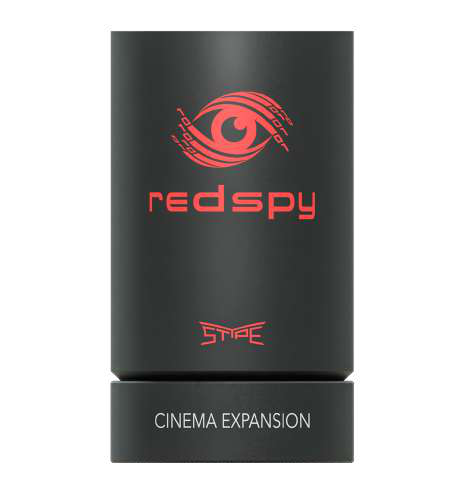
**RedSpy 影院扩展模块(Cine Expansion Module)** 可让系统使用 Cooke /i Technology 或 Zeiss eXtended Data 协议,直接从镜头本身读取镜头与畸变数据。RedSpy 相机叠装在该模块顶部,模块背面则提供一组额外端口。
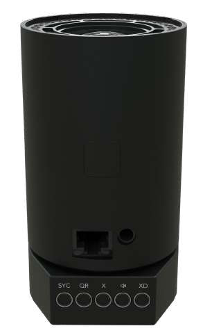
**Watcher X** 是一款无标记(markerless)追踪配件,让 RedSpy 系统在标记点地图被完全遮挡或不在视野内时仍能可靠追踪相机。在片场,它让相机设备能顺畅地进出狭窄空间(如车辆内部),或贴近各类布景下方移动,而不损失追踪质量。在外景拍摄时,它的传感器可对物理环境建图,从而完全省去回反射标记点。在 RedSpy 系统已配置好的前提下,设置 Watcher X 非常简单:推动相机设备绕场走一圈完成区域建图,再捕捉四个参考位置,使生成的地图与主标记点地图对齐即可。
# 设置向导:分步指引
## 1 放置标记点
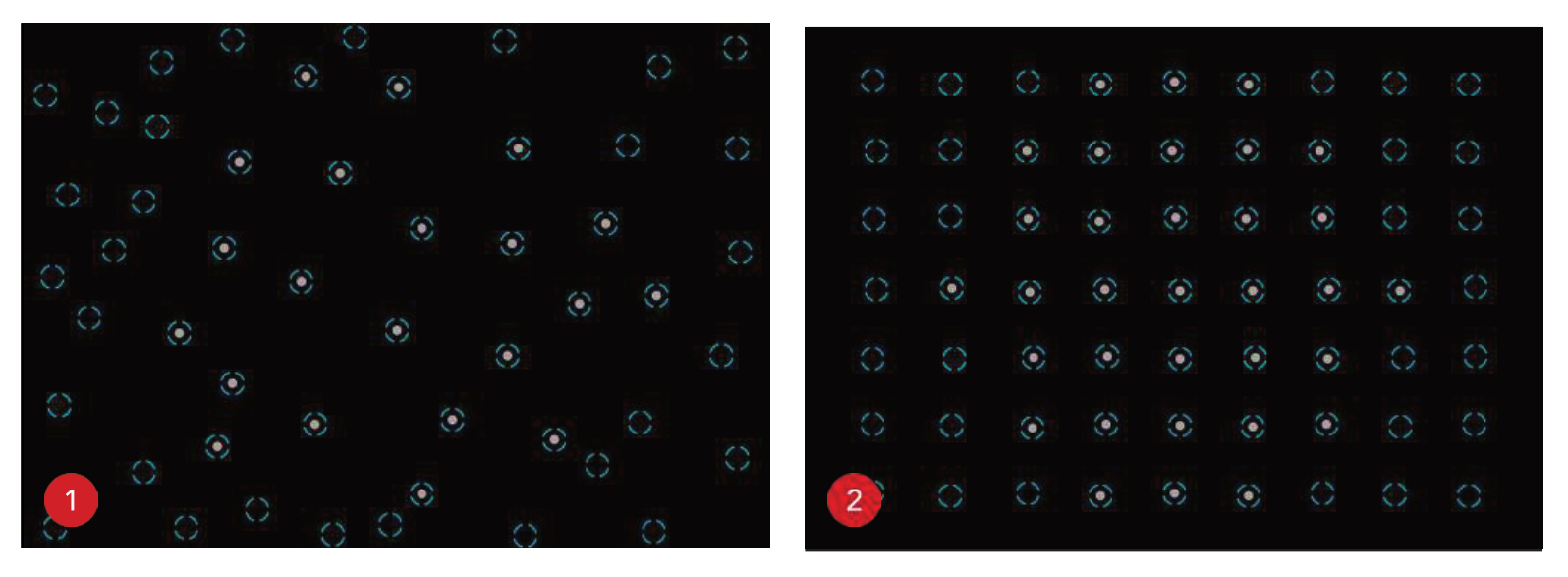
虽然也有其他做法,但安装回反射标记点最常规的两种方式,是把它们布置在天花板(首选)或地面上。请根据你的具体情况选择最合适的方式。无论哪种方案,标记点的尺寸以及相邻标记点之间的推荐间距,都取决于 RedSpy 相机到标记点阵的平均距离。当然,标记点的总数还取决于要实现相机追踪的区域大小。如果你拿不准要用多少标记点,宁可偏少、间距偏大,也不要反过来。标记点阵密度过高,对追踪质量的负面影响,比略微偏低更明显。
> **安装标记点时请遵守以下规则:**
>
> - 标记点必须贴在平整的表面上。
> - 标记点的排布要尽量不规则,尽可能避免重复的图案。
> - 整个标记点阵中,相邻标记点之间的间距要保持在一个允许的范围内。
## 2 建图
对标记点阵建图,是让 RedSpy 有机会登记并记住各个标记点的位置,将它们转化为"检测点",之后系统就能据此识别自己在片场中的位置。
### LED 亮度与检测阈值
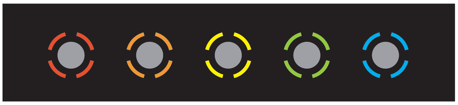
检测环(reticle)是把回反射标记点与环境中偶然反射区分开来的标志。它表示某个反射已被判定为标记点,而环内灰色圆圈的直径则反映该反射的强度。开始对新区域建图时,检测环最初会显示为红色。随着操作推进、系统逐步记住地图布局,检测环的颜色会根据某个检测点的可靠程度逐渐变化。最终,所有标记点都应呈现为青色检测环。
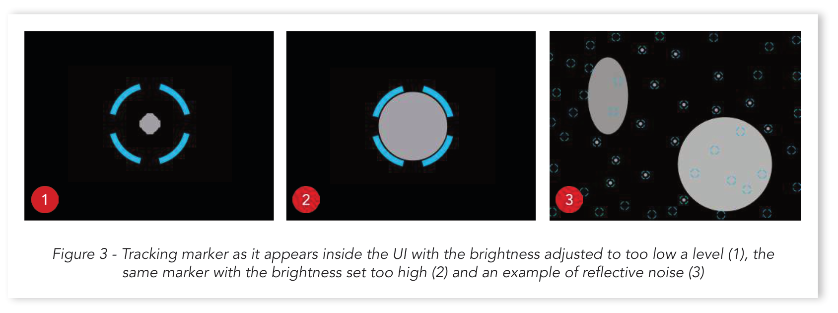
在对影棚建图之前,务必先把红外 LED 的 `BRIGHTNESS`(亮度)和检测 `THRESHOLD`(阈值)调到合适的水平。RedSpy 相机离标记点阵越远,所需的 LED 亮度就越高,才能产生可靠的检测。提高检测阈值有助于排除来自螺柱、螺钉头或天花板上各种凸出金属件的微弱、不规则反射;反之,降低阈值则能让 RedSpy 依靠不太显眼的标记点进行追踪,增加视野内的检测点总数,但同时也会加大处理负荷。
两个滑块都应在适中范围内调节,避免取极端值才能得到最佳效果。一条经验法则是:把它们调到能让标记点反射与其检测环之间留有一定空隙。把红外 LED 的 `BRIGHTNESS` 调得太高,会导致检测环最终从标记点上完全消失——使其失去追踪意义。同样,把 `THRESHOLD` 降得过低,会让检测范围扩展到环境中各种非标记物体上,进而损害追踪。
灰色椭球状形状清楚地表明 RedSpy 视野中存在反射噪声。减少直接挡在追踪相机视线上的障碍物(例如摇臂头),能在很大程度上避免它们;或者,也可以通过调节上述两个参数来减轻它们的干扰。
### 建图流程
建图应从影棚空间的中心开始,可以手持 RedSpy 相机,也可以把它已经装在相机设备上。建议让它与天花板表面保持正交,并在整个过程中保持绕对称轴的朝向和离地高度一致。在最初的建图阶段,动作应缓慢而审慎,注意不要用手、头或宽松的衣物从相机视角遮挡标记点。初始化阶段一过,RedSpy 就能适应更快的动作。操作时请跟随界面中的视觉提示:红色、橙色和黄色检测环表示该标记点的确切位置尚未确定;一旦检测环变为青色,它在标记点阵中的位置就已完全确定。
最佳做法是:RedSpy 操作者从片场中央的同一个原点出发再返回,反复地、循序渐进地"啃下"标记点阵中尚未记住的部分。任意时刻,红色检测环的标记点都不应超过相机视野的 1/3。建图完成后,选择 `STOP EXPANDING` 并保存地图。切换到 `TRACK` 视图,可以通过在片场中走动来检查地图质量。当 RedSpy 相机移动时,若出现过长的标记点拖尾,就说明是错误检测;这类标记点可以、也应当从地图中删除。
> **启动时的陀螺仪校准**
>
> 每次主机启动时,都需要给 RedSpy 相机留出足够时间来校准其陀螺仪传感器。如果此时还没装到相机设备上,只要红色提示图标还在闪烁,就让它静置在稳固、平整的表面上。等闪烁停止、图标消失后,就可以继续对影棚建图了。
## 3 地图校准
### 地板对齐(Floor Align)
地图校准从 `FLOOR ALIGN` 开始,让系统把标记点阵放到真实的影棚空间中去理解。继续操作:把 RedSpy 相机放到至少三个不同的位置上,尽量覆盖更大的片场范围,准备好采集时按下 `+` 按钮。务必保证每个采集点到天花板的距离完全一致——最简单的办法是把它直接放在地面上。对于地面安装的标记点,可以借助三脚架、移动车或 C 形架等保持各采集点的高度一致。和之前一样,采集位置时让 RedSpy 相机垂直于标记点所在表面。
> **使用 Action 按钮**
>
> 除了在界面上操作,你也可以通过 RedSpy 相机侧面的 Action 按钮来选取各个采集点。每次按键指示灯都会亮起。对采集到的位置数量满意后,长按 Action 按钮 3 秒即可退出 `FLOOR ALIGN` 菜单。
### 设定比例(Set Scale)
标记点地图的比例,由两个独立采集点之间测得的距离来定义。这两个位置应尽量远离,但仍要落在标记点阵范围之内。对于矩形地面布局,它们应位于一条横贯该区域的假想对角线的两端。先把一件物品贴着 RedSpy 相机机身放置,作为参考来标记第一个位置。然后把相机移到第二个位置,用激光测距仪测量参考物到相机的距离。注意让 RedSpy 绕对称轴的朝向在两个采集点上保持一致。
## 4 定义虚拟影棚(设定零点)
### 设定零点与零位偏摆
`ZERO POINT`(零点)表示物理空间中的一个位置,对应虚拟场景的原点。
`ZERO PAN`(零位偏摆)则定义一条与渲染引擎默认前向轴重合的直线。
把 RedSpy 相机放在视觉艺术家据以搭建场景的合适位置上,按 `>` 按钮或按一下 Action 按钮来确认你的选择。然后,再次保持 RedSpy 相机朝向一致,沿所需路径把它尽量移远,画出一条线段——从而最终确定追踪坐标系相对于周围环境的位置。
## 5 安装 RedSpy 相机
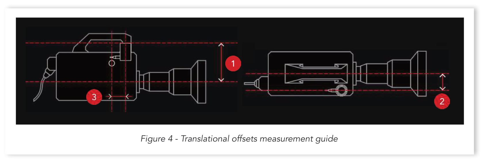
要追求极致清晰的追踪精度,准确定义 RedSpy 的 CMOS 与影棚相机传感器之间的空间关系是关键前提。用随附的安装支架之一把 RedSpy 牢牢固定到相机设备上。然后,根据你选定的安装位置,指定它网线指向的方向。接着测量第一个平移偏移:从影棚相机光轴到 RedSpy 机身顶边(1)。第二个偏移确定 RedSpy 在横轴方向上偏离中心多远(2),第三个则测量从影棚相机焦平面到 RedSpy 对称轴的距离(3)。请仔细测量这些距离,并对照界面提示进行。
## 6 设置 IP 地址
### 设置源 IP 地址
默认设置假定 RedSpy 主机与它要发送追踪数据的渲染工作站位于同一子网,CIDR 为 /24——即子网掩码为 255.255.255.0。如果工作站被分到另一个独立网络,可以借助 `Gateway IP`(网关 IP)来访问它们。主机也可以向为此配置的 DHCP 服务器租用地址。继续操作:在 `Source IP` 下输入想要的静态 IP,或勾选 `DHCP` 复选框。
### 设置目标 IP 地址
每一个目标设备都可以使用不同的追踪协议,而追踪延迟的调整则统一适用于所有设备。两者都可以通过点击目标 IP 地址旁边的 `EDIT` 来配置。注意不要分配渲染工作站上已被其他网络进程占用的端口。完成后,用 ping 按钮对目标设备执行网络连通性检查。
## 7 精细调校
至此所有 RedSpy 基础系统都已就位,我们可以借助一个简单的校准场景来精细调校追踪表现了。向导根据影棚相机是可移动还是固定,提供两套不同的精调流程。虽然必须在一开始就做出选择,但两种情形的初始步骤是相同的,因此本手册会在后面再区分二者。
从列表中选择你的相机,并选定正在使用的分辨率。相机会根据所设分辨率,在每一帧只扫描传感器的一部分。了解成像传感器的这一有效宽度,对于在不同类型相机间无缝复用镜头文件至关重要。此外,要成功使用 stYpe 庞大的镜头文件库,也需要熟悉传感器的尺寸参数。对于一些主流相机品牌,只要你输入型号和录制模式,有效传感器宽度就会自动确定。如果列表里没有你的相机,请查阅其用户手册并手动输入传感器宽度。
每个 RedSpy 版本都附带大量针对常用广播镜头的基准镜头文件。你可以在这些文件基础上继续构建,也可以通过选择 `Default` 预设从零创建一个全新文件。如果没有适合你所选镜头的基准镜头文件,就挑一个焦段范围最接近的。之前创建或导入的镜头文件,可以通过 `MY LENSES` 菜单访问。
> **基准镜头文件——管理预期**
>
> 同一品牌、同一型号的两支镜头,畸变特性也可能相差很大。即便理论上能精确匹配,通常也需要做一些调整,才能充分发挥基准文件的作用。
### 镜头量程(Lens Ranges)
在使用内置编码器还是外置编码器之间做选择。使用内置编码器时,把随附的佳能或富士能镜头线分别接入 Virtual 或 EXT 端口,以接入镜头数据流;线缆另一端的 LEMO 接头插入 RedSpy 相机上的镜头数据端口。借助可选的影院扩展模块,还可以使用 Cooke /i Technology 或 Zeiss eXtended Data 协议,直接从镜头本身读取镜头与畸变数据,而无需依赖外部镜头文件。
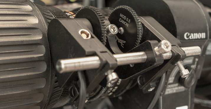
使用外置编码器时,必须确保它们的齿轮与镜头齿圈可靠啮合。每个编码器都有一块弹簧加载的底板,上面有两个通孔,其中一个会套在编码器安装轴上,而该轴又由镜头托架固定。各编码器的朝向可根据空间限制而变化;但套在安装轴上的那个通孔,应统一选用离镜头中心线较远的那一个。这样就能利用弹簧张力让齿轮保持啮合。扫描下方二维码可观看编码器安装视频教程。装好后,指定菊花链中哪个编码器追踪变焦,并让它们走完整个行程。每次系统重启时都需要这样做。对于没有硬限位的镜头,校准过程不一定是不言自明的:转动对焦环到达最近对焦距离,注意不要转过头,在界面中确认这个位置;接着转到无穷远对焦,再多转四分之一圈,然后再继续。
### 准备场景
在你选用的渲染引擎中创建校准场景非常简单:往关卡里插入一个倒置的圆锥网格,把它摆放到锥尖正好落在世界原点(0,0,0)的位置。再把剩下的一个追踪标记点贴到影棚相机正对的墙面上,高度大约与相机水平时的成像传感器持平。在接下来的几个步骤中,你将根据渲染引擎给出的提示来调整一系列追踪参数。
让相机与墙面保持适当距离,然后变焦推到最长端。调整偏摆和俯仰,让取景器十字线与标记点对齐。测量从相机传感器到墙面的距离。此时 RedSpy 会临时把零点重新放到追踪标记点的中心;精调完成后,它会自动恢复到我们在 `Define Virtual Studio`(定义虚拟影棚)阶段所指定的那个点。回看渲染引擎视口,AR 圆锥的尖端此时应正好位于标记点中心。
### 调整镜头中心
`Center Shift`(中心偏移)用于补偿不同焦段下画面的垂直和横向偏移。每次给机身换上一支新镜头,都需要重新做这项调整——不同卡口在镜头与传感器对齐的一致性上有差别(例如 PL 卡口就比 EF 更一致)。在相机仍处于最长焦端的前提下,变焦拉到最广的画面。观察圆锥此时已不再位于标记点正中心。用 `Left-Right Offset`(左右偏移)和 `Up-Down Offset`(上下偏移)滑块调整中心偏移值,让圆锥重新对准标记点中心。然后再次变焦推近标记点,这一次用同一组滑块精确地重新调整临时零点的位置。等圆锥回到标记点中心后,再变焦拉远,反复执行上述步骤,直到无论变焦到哪一档,圆锥尖端都精确居中。如果用的是定焦镜头,可整段跳过。
> **全局中心偏移与局部中心偏移**
>
> 有些镜头在焦段两端都能让圆锥与标记点中心完美对齐,但在其他变焦档位上却会游移不定。这种情况可以在之后的 `EDITING LENS TABLE`(编辑镜头表)阶段补偿:为不同变焦档位指定不同的中心偏移值,而不是只做一次统一的全局调整。
接下来要对 RedSpy 的旋转偏移做细微调整,因为 `TILT`、`PAN` 和 `ROLL` 的默认值(分别为 90、0、-180 度)多半不会正好匹配追踪相机的实际位置。
#### 追踪精调 [偏摆 —— 边缘]
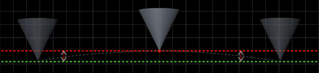
变焦拉到最广,左右摇动相机。观察圆锥尖端是否在屏幕上划出一条倾斜的轨迹。如果是,就调整 `Up-Down Offset`,直到圆锥划出的轨迹变成一条开口向下的抛物线、其顶点正好位于标记点中央——也就是说,让圆锥尖端在画面两侧边缘处与标记点中心的垂直偏移相等。此阶段我们的镜头文件多半还很不完善,所以并不指望圆锥能在画面里随标记点水平移动。现在只专注于它的垂直运动。
到这里,设置流程会根据本节开头选择的是"可移动"还是"固定/半固定"相机运动而分叉。
### 7A 可移动相机
#### 追踪精调 [移动相机]
变焦完全推近标记点,向前推轨(dolly),直到界面显示相机处于近标记点位置。用滑块重新调整圆锥位置,让它位于标记点中心。然后把相机推离标记点到达远位置,必要时再调整滑块。同样反复执行这两步,直到圆锥在整条推轨路径上都与标记点贴合。
### 7B 固定 / 半固定相机
#### 追踪精调 [偏摆 —— 中心]
静态相机的精调过程相对简单,但仍有一些步骤需要完成,才能充分发挥追踪系统的能力。整节都保持广角画面。继续从左到右摇动相机,用 `Up-Down Offset` 把上一步描述的那条抛物线压平。调整滑块会让圆锥偏离标记点中心。当圆锥在不同偏摆角度下都与那条假想水平线保持相同的垂直距离时,即可继续。

#### 追踪精调 [俯仰]
把相机一直俯到底、再一直仰到顶,直到圆锥尖端到达画面的最边缘。观察圆锥尖端并非沿一条完全笔直的垂直线移动,而是划出一条曲线,此时它像一条水平方向的抛物线。调整 `Left-Right Offset`,直到圆锥的水平位置不随俯仰角变化而保持稳定。
旋转偏移调好后,剩下的就是设置镜头表和对焦距离表了。最后这两节适用于所有设置,无论相机是否可移动。
### 编辑对焦距离
设置对焦距离表,能让 AR 图形根据其相对于虚拟相机的位置以及当前对焦距离呈现准确的清晰度,从而模拟周围物理环境的清晰度层次。
你可以手动测量相机焦平面与参考物在其逐渐远离过程中的距离,也可以直接输入镜头本身刻印的对焦距离标记值。采用后一种方式时,相机必须经过正确的法兰距校准,即镜头事先完成后焦校准。
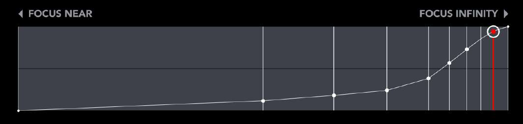
进行 `MANUAL FOCUS DISTANCE MEASUREMENT`(手动对焦距离测量)时,变焦推到最长端,并把镜头调到最近对焦距离。把参考物紧贴相机,直到它合焦。完成第一次测量,选择 `Edit 0 Focus` 并输入测得的值。然后把参考物从相机前移远一些,再让它重新合焦。选择 `+ ADD DOF POINT`,测量并输入距离。对最多 8 个不同的对焦距离重复这些步骤(不含无穷远对焦)。把更多测量点集中在对焦行程的尾端,因为对焦环每调整一点,对焦距离在这里的变化都相当快。
### 编辑镜头表
前面已经提到,每支镜头都有自己独特的畸变特征。渲染引擎在把场景映射到屏幕空间时,必须把这些畸变考虑进去。它必须按照镜头透视可靠地扭曲 AR 图形,才不会破坏合成画面的沉浸感。在这样做时,它会依赖镜头校准过程中采集到的数据点。
整个设置过程中可以明显看到:每当相机的偏摆角度过大,圆锥就会在物理空间中失去定位。通过调整 `FOV` 滑块来校准镜头文件,能让圆锥无论相机如何运动都保持其位置。
从镜头的最短焦距开始,逐步推向最大变焦。先向一侧摇动相机,把追踪标记点摇到画面边缘三分之一处的位置。调整 `FOV` 值,直到圆锥重新对回原来的位置。再稍微多摇一点,让标记点到达画面边框三分之二处,重新调整 `FOV`,直到圆锥再次与标记点对齐。最后,一直摇到把标记点摇到画面轮廓边缘,重复这项调整。然后把相机摇向另一侧,必要时再微调 `FOV` 值。当圆锥无论影棚相机偏摆到什么角度都稳稳停在标记点中心时,就可以继续下一个变焦档位。
> **折中取舍**
>
> 有可能出现这种情况:向左摇时刚好合适的 `FOV` 值,向右摇时效果却没那么理想。遇到这种情况,就在两个位置之间取折中值,从而把图形漂移的总量降到最低。
设置阶段至此完成,给配置文件起个名字并保存。为配置文件设置密码保护,可防止它被误删。多个配置文件让你在不同影棚之间、以及使用多台不同影棚相机时,都能快速高效地切换操作。
# RedSpy 用户界面总览
## 主屏幕
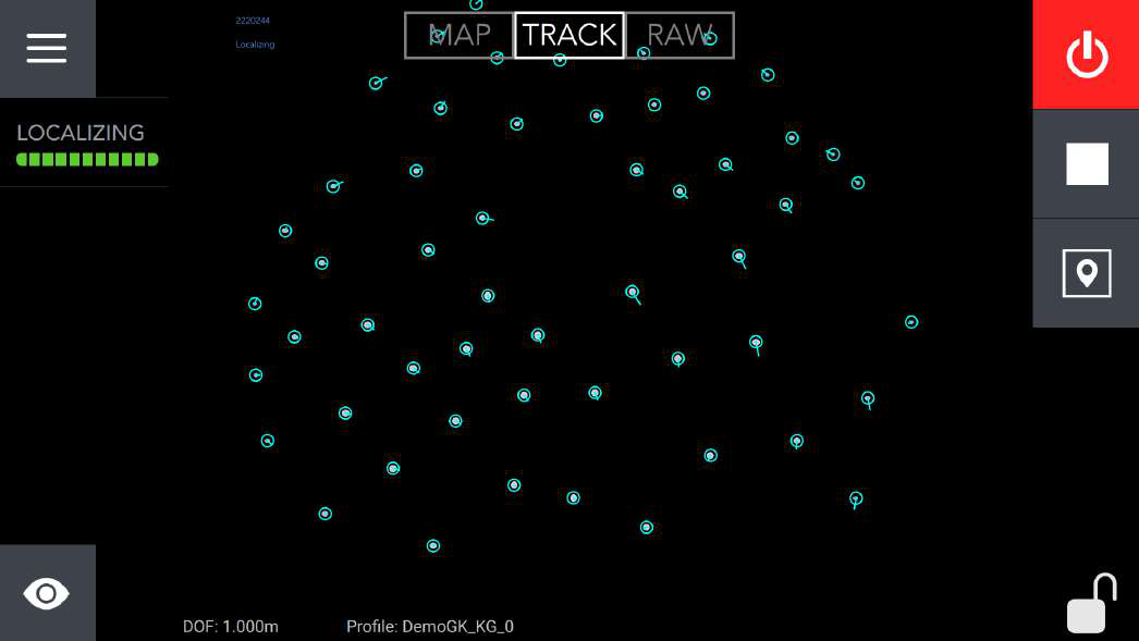
1. 在主屏幕与 RedSpy 标签页界面之间切换。
2. 查看发往各目标设备的追踪数据概况。在 `Protocol`(协议)字段上三击,可在 FreeD 与 StypeHF 追踪数据之间循环切换。读数会显示 LOCALIZING(定位中)或 EXPANDING(扩展中),具体取决于右侧开关(9)的设置。下方的健康度条则反映标记点地图的质量。
3. 长按可自定义状态列表。可在以下选项中挑选:
- **GENLOCK** —— 查看当前系统帧率。打勾表示参考信号已接入。若没有同步信号发生器,RedSpy 会默认采用每秒 55 帧。
- **GYRO** —— 每次 RedSpy 系统开机时,相机的陀螺仪传感器都会进行一次校准。只要红色提示图标还在,就让影棚相机保持静止。校准完成后,图标会变为打勾。
- **LENS RANGES** —— 如果对焦和变焦值显示为红色,说明编码器量程尚未设定。设定方法是让对焦环和变焦环各自走完整个行程。每次系统重启时都需要这样做。
- **WARNINGS** —— 显示当前系统警告。
- **LTC** —— 时间码读数。
- **Record** —— 触发内置的追踪数据记录器。生成的 .xml 文件会保存在 RS3MainServer 目录下的 Recording 文件夹中。
- **RED** —— 启用 RED 相机控制界面。
- **THRESHOLD** —— 直接在主屏幕上调整检测 `THRESHOLD`(阈值)级别,同时能清楚看到标记点。
- **MASKING** —— 把带有特别长拖尾的反射或标记点遮蔽掉,可减小片场某个特定位置的重投影误差。常规遮罩对静态镜头已经够用;而动态遮罩则可以在保留地图其余部分不被遮挡的前提下,只在影棚相机俯仰角足够大时才挡住某个特定表面。
- **WATCHER X** —— 要对区域建图,在 `GENERAL`(常规)标签页下点击 `RESTART`,然后缓慢移动相机设备绕场。`Map Match`(地图匹配)值表示 Watcher X 当前对周边环境的感知精度,而 `Scene Detail`(场景细节)则反映它所采集的图像中信息是否充分。当这两个指标在整个区域内都持续保持在 100% 左右时,选择 `SAVE` 保存。最后,在 `SETUP`(设置)标签页下选择 `MANUAL ALIGN`(手动对齐)或 `AUTO ALIGN`(自动对齐),把 Watcher X 地图与基准标记点地图对齐。根据你想为某个场景使用的追踪数据组合,把 `DATA TYPE`(数据类型)在 `REDSPY`、`WATCHER X` 或 `COMBINED`(组合)之间切换。
4. 点击左下角的 RedSpy 图标可调出 RedSpy 工具栏。在这里可以快速切换不同的镜头文件、加载任意已保存的配置文件,或重启主机。
5. 在 `MAP`(地图)与 `TRACK`(追踪)视图之间切换。打开 `RAW`(原始)后,点击并拖动,即可把标记点阵叠加到 RedSpy 的纯净相机画面上。在排查某个棘手反射的确切来源时,这一点尤其有用。
6. 当前选用的配置文件。一旦做了任何更改,系统会提示用户把更改保存为新的配置文件。
7. 开启或关闭 RedSpy 相机。
8. 启动和停止相机追踪。
9. 在定位(localizing)与扩展(expanding)模式之间切换;用扩展模式向当前地图添加新的检测点。
10. 长按可锁定屏幕,防止误改任何设置。
## 网络
通常情况下,主机与目标设备(即渲染工作站)位于同一个共享子网,并使用静态 IP 地址。用 `Source IP` 文本框设定主机的 IP 地址。然后在 `Subnet`(子网)下输入相应的 CIDR 数值,选择想要的子网掩码。
也可以让 DHCP 服务器为主机和周边网络设备租用 IP 地址。这种情况下,设置非常简单:勾选界面右上角的 `DHCP` 复选框即可。
ping 按钮通过对某个目标地址发送 ping 来执行网络连通性检查,而移除按钮则把某个地址从列表中删除。落在所定义子网之外的地址,以及不慎被重复列出两次或更多的目标,都会以红色高亮显示。
## 相对主相机的偏移
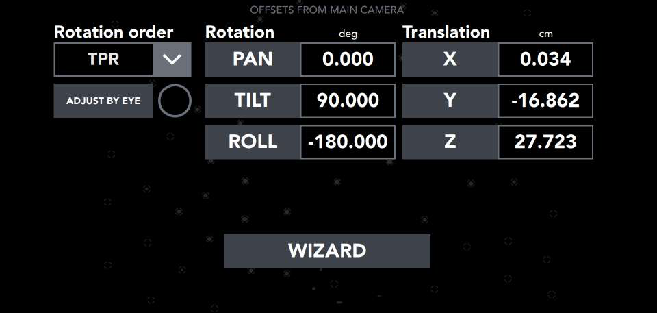
旋转偏移和平移偏移用于准确定义 RedSpy 相机相对于影棚相机成像传感器的位置。
当 RedSpy 的朝向以 `PAN`、`TILT`、`ROLL` 均为 0° 起算时,描述的是这样一种位置:它的 RJ45 端口正对地面朝下,LED 环朝向与影棚相机镜头相同。最常用的安装位置是 RS 朝向天花板、网线伸向相机设备的后方。在默认的 TPR 旋转顺序下,这就需要把 `TILT` 调到 90°、`ROLL` 调到 -180°。
`X`(左右偏移)从影棚相机光轴量到 RedSpy 的对称轴。以相机操作员的视角看,正偏移表示 RedSpy 偏离中心、位于右侧;若位于左侧,则把测得值输入为负数。`Y`(上下偏移)从 RedSpy 机身顶部量到影棚相机光轴。当 RedSpy 装在影棚相机上方时其值为负,装在下方时为正。`Z`(前后偏移)从 RedSpy 的对称轴量到影棚相机焦平面(焦平面位置通常标在机身侧面)。当 RS 装在焦平面前方时为正,装在后方时为负。
如果不确定上述任何测量该怎么进行,或不确定你这套安装该用什么旋转偏移,选择 `WIZARD`(向导)即可进入偏移的可视化指引。
> **偏移精调**
>
> 每次把 RedSpy 相机从相机设备上取下再重新装上,两个成像传感器之间的相对位置都会有极其细微的变化。因此,每遇到这种情况,都务必重新执行 7A 或 7B 节所述的精调流程。
## 建图
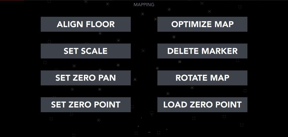
建图标签页分为两列:左侧的操作是必做的,每次对新影棚建图后都要执行。它们完成地图校准过程,让系统把标记点阵放到真实影棚空间中去理解。相反,右侧的操作是可选的,只在特定情况下才需要考虑。
`ALIGN FLOOR`(地板对齐)定义标记点阵相对于地面的对齐基准。至少需要 4 次采集。各采集点都让 RedSpy 相机与标记点阵保持相等距离,并尽量覆盖更大的片场范围。
`SET SCALE`(设定比例)确定系统所感知的标记点地图大小,并使其与实际片场尺寸匹配。选取两个采集点并测量它们之间的距离。这两个位置应尽量远离,但仍要落在标记点阵范围之内。先把一件物品贴着 RedSpy 相机机身放置来标记第一个位置。然后把相机移到第二个位置,用激光测距仪测量参考物到相机的距离。让 RedSpy 绕对称轴的朝向在两个采集点上保持一致。
`ZERO POINT`(零点)表示物理空间中对应虚拟场景原点的一个位置。把 RedSpy 相机放在视觉艺术家据以搭建场景的合适位置上并采集一次。如果 RedSpy 已经装在相机设备上,就不要输入 0,而是输入影棚相机光轴与零点应落在的表面之间的高度差。这样就能在不取下 RS 相机的情况下重新调整零点位置,因而也不会影响旋转偏移。
`ZERO PAN`(零位偏摆)在物理空间中画出一条与虚拟场景默认前向轴重合的直线。保持 RedSpy 相机绕对称轴的朝向一致,把它放在一个初始点,然后沿所需路径尽量移远,画出一条线段。
> **地图质量评估**
>
> 按特定顺序执行地图校准步骤,就能同时检查地图本身的质量。完成 `ALIGN FLOOR` 后,标记第一个 `SET SCALE` 位置,移动相机并输入测得的距离。让相机停在这个位置,放下 `ZERO POINT`,再选择 `ZERO PAN`。完成第一次采集,把 RS 拿回起始位置完成第二次采集。回到主屏幕,选择 LOCALIZING 查看追踪数据概况。启用 FreeD 协议,检查正在输出的位置数据。假定影棚地面完全平整,X 和 Y 都应读为零,而 Z 值应与设定比例步骤中测得的距离一致。
`OPTIMIZE MAP`(优化地图)通过添加各种类型的关键帧,或手动把若干追踪标记点指派到同一个平面上,来补充现有的地图信息。每个关键帧都会同时捕捉一张标记点阵的快照,并记录 RedSpy 相机当时的位置。把这些数据喂给优化算法,会让整张地图中的标记点位置得到细化。
我们把关键帧分为常规关键帧和平面关键帧。常规关键帧可以手动采集,也可以在你绕影棚走动时由系统自行决定何时采集而自动收集。平面关键帧则必须手动添加,操作者要确保每一次快照都让 RedSpy 相机与标记点阵保持完全相同的距离。收集到一组关键帧后,选择 `Optimize`(优化)触发优化过程。建议先只依靠常规关键帧来细化地图;只有当第一轮优化效果不理想时,才再添加平面关键帧或选择平面标记点。
随着关键帧不断添加,标记点会根据它们在不同快照中被捕捉的次数而以不同颜色高亮:
- **蓝色** —— 标记点尚未被捕捉。
- **红色** —— 标记点被捕捉不超过两次。
- **黄色** —— 标记点被捕捉了三次或四次。
- **绿色** —— 标记点在 5 次或更多快照中被捕捉。
这提供了有用的反馈,因为每张新快照都收集一组完全不同的标记点并没有太大意义。必须存在重叠,优化算法才能达到预期效果。
自动采集关键帧的判定标准,可以通过设置菜单输入两个参考关键帧来重新定义。这两个参考关键帧的采集距离,不应超过 RedSpy 相机到标记点阵距离的两倍。`Reset`(重置)按钮可把判定标准恢复到默认状态。
切换到 `Markers`(标记点)可添加平面标记点。选取不超过标记点总数 5% 的、你确信都位于同一平面上的标记点。在优化运行期间,`Optimize` 按钮会显示为 Stop(停止)。一旦按钮恢复正常,地图细化过程就完成了。
`ROTATE MAP`(旋转地图)可对 `ZERO POINT` 做精确调整,让 AR 图形与真实布景之间实现完美对齐。在同一影棚中使用多套 RedSpy 系统时,这项功能尤为重要。与早期 RedSpy 版本不同,一旦做出调整,它会立即覆盖现有的对齐数据,同时全部六个输入字段归零。此后每一次更改,都以前一组调整所定义的当前虚拟空间对齐为基准来进行。
`LOAD ZERO POINT`(加载零点)把之前在另一个配置文件中定义的零点应用到当前配置文件上。
## 滑块
`Translational Smoothing`(平移平滑)用于消除经过标记点地图中某个特别"粗糙"的区域时可能出现的图形抖动。这种抖动在使用更长焦段拍摄时往往更明显,因此可以分别为长焦和广角镜头调整平滑程度。多数情况下,保持默认值最好。
RedSpy 始终把基于追踪标记点星座推断的自身位置与 IMU 数据相互参照。通过调整 `Gyro Influence`(陀螺仪权重),可以让这种关系偏向一方或另一方。调高它会增加系统对陀螺仪漂移的敏感度,同时也提升它对标记点地图偏差的抗扰能力。建议保持默认值。
`Led Brightness`(LED 亮度)和 `Detection Threshold`(检测阈值)——RedSpy 相机离标记点阵越远,所需的 LED 亮度就越高,才能产生可靠的检测。提高检测阈值有助于排除来自天花板上各种凸出金属件的不规则反射;反之,降低它则能让 RedSpy 依靠不太显眼的标记点进行追踪,增加视野内的检测点总数,但也会加大处理负荷。两个滑块都应在适中范围内调节,避免取极端值才能得到最佳效果。一条经验法则是:把它们调到能让标记点反射与其检测环之间留有一定空隙。
> **主动式标记点**
>
> 配置为配合 LED 背景墙上投射的主动式标记点工作的系统,会向用户多提供两项设置。`Exposure`(曝光)顾名思义,定义 RedSpy 相机的快门速度,应根据环境光水平和 LED 背景墙亮度来调整。`Led Duration`(LED 持续时间)在 RS 的帧节奏中引入一个相位偏移,借此让 RedSpy 的帧捕捉与显示标记点阵的交错帧精确同步。当使用帧重映射(frame remapping)或同类技术时,这一点变得相关。
`Tracking Data Delay (Frames)`(追踪数据延迟,帧)在视频信号流的延迟大于网络延迟的环境中,让追踪数据与相机画面同步。通过摇动相机并观察 AR 元素的表现,来评估网络延迟与视频延迟之间的关系。如果图形看起来在相机运动之前就提前重新调整了自己的屏幕空间位置,那就是追踪数据帧比视频信号更早到达渲染引擎的明显迹象。反之,如果追踪数据落后于视频画面,就需要在渲染引擎一侧引入一些视频延迟,同时把追踪数据延迟滑块保持在最小值。
`Data Sampling Sub-Frame Delay`(数据采样亚帧延迟)可对追踪延迟做进一步精调,以总帧时间 5% 为步进调节。它只有在勾选 `PTS` 复选框后才相关。它调整同步单元的缓冲,以正确把握发出追踪帧的时机,从而尽量减少系统对外推帧的依赖。
`Data Rate`(数据速率)设置可让 RedSpy 帧率与影棚相机帧率匹配,适用于同步信号发生器以项目帧率的整数倍或整数分之一运行的情形。拍摄慢动作素材时,这项功能经常用到。
被追踪的相机位置会不断被镜头文件所定义的节点距离偏移,以产生渲染图形逼真的视差误差。`Ignore nodal DOF`(忽略节点景深)指示系统停止按该节点距离调整对焦距离。除非你的特定工作流另有要求,否则该选项应保持不勾选,因为它会让 AR 图形无法与真实环境同步地进出焦点。
`Jumbo`(巨型帧)复选框:只要在 RedSpy 相机与对应主机之间中转信息的网络接口支持大于 1500 字节的帧,就应启用它。请相应地配置网络交换机上的 MTU 设置。整个地图界面间歇性闪烁,是 MTU 瓶颈导致丢帧的明显迹象。
启用 `PTS`(数据包时序稳定)会让追踪数据从主机的 RS CAM 端口发出,而非 EXT LAN 端口。这种情况下,RedSpy 相机、主机和目标设备都插接到同一台 PoE 交换机上并通过它通信。使用 PTS 会增加整体追踪延迟,但也能确保追踪数据以更均匀的帧时间送出。
## 镜头校准
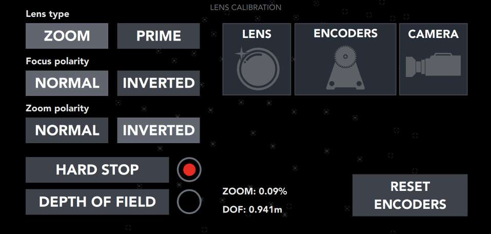
如果启用了 `Auto Start`(自动启动),系统会在开机后立即开始追踪相机。根据外置编码器的安装方式,有时需要反转其极性,才能让实际的镜头环位置与相应的编码器读数对应。归一化后,对焦在镜头调到无穷远时读数应为 100%,变焦在镜头调到最长焦距时读数应为 100%。
默认情况下,系统会假定最外侧的编码器(编码器 2)追踪对焦,最内侧的(编码器 1)追踪变焦。选择 `ENCODERS`(编码器)可重新排列菊花链中各编码器的位置。
启用 `DEPTH OF FIELD`(景深),可把对焦值输出为对焦距离;禁用它,则输出 0 到 1 之间的归一化对焦读数。
通过 `LENS`(镜头)菜单,你可以加载另一个镜头文件、对当前文件做调整,或基于某个内置基准文件新建一个全新文件。每一个镜头文件都由四个不同的组成部分构成,它们共同让渲染引擎能准确、可靠地扭曲 AR 图形,使其与镜头透视对齐:
- **`ADJUST CENTER SHIFT`(调整中心偏移)** —— 每次给机身装上一支镜头,它相对于成像传感器的位置都会略有不同。也就是说,镜头中心永远不会真正与传感器中心重合。由于这一微小的错位,变焦推近时取景会与上次换镜头时略有差异。中心偏移用于补偿这一点,确保图形无论变焦到哪一档都牢牢锚定在原位。镜头表和对焦距离表是"一次设好、一劳永逸"的,而中心偏移则需要每次重新装镜头时都重做。
> **调整中心偏移**
>
> 先在渲染引擎中启用中心偏移标记点叠加,然后:
>
> 1. 变焦完全推近,让标记点与你选定的某个参考物对齐。
> 2. 变焦拉到最广画面,观察中心偏移标记点如何从参考点偏移开。
> 3. 用滑块把标记点重新调回与所选参考物对齐。
> 4. 变焦完全推近,通过摇动和俯仰相机重新构图,让中心偏移标记点再次落在参考点上。
>
> 反复执行第 2 到第 4 步并细化中心偏移值,直到无论变焦到哪一档,中心偏移标记点都稳稳停在原位。如果中心偏移标记点在焦段中段总是偏离参考点——尽管它在特写端和广角端都能对位——那么这支镜头可能需要在不同变焦档位采用各自不同的中心偏移值,而不是一次统一的全局调整。这可以在 `EDIT LENS TABLE`(编辑镜头表)菜单中调整。
- **`LENS TABLE`(镜头表)** —— 每支镜头都有自己独特的畸变特征。渲染引擎在把场景映射到屏幕空间时,必须把这些畸变考虑进去。在某个参考物上叠加一些图形作为参照,以便对 `FOV` 值进行调整。摇动相机,注意观察随着偏摆角度增大,图形如何从它本应锚定的物体上漂移开。用 `FOV` 滑块把图形重新对齐,并对每一个变焦档位重复这一过程。
- **`FOCUS DISTANCE TABLE`(对焦距离表)** —— 把一件参考物举在相机前,镜头设到最近对焦距离,变焦完全推近。在参考物清晰合焦的状态下,测量它到相机焦平面的距离,选择 `Edit 0 Focus` 并输入测得的值。此后每测一个新点,就把参考物从相机前移得更远一些。
- **`SET SENSOR SIZE / CROP SENSOR`(设定传感器尺寸 / 裁切传感器)** —— 把一个最初用更大传感器的相机校准出来的镜头文件按比例缩小。
## 配置文件
可在加载、保存或导出配置文件之间选择。为防止不可逆地破坏一套已可用于播出的设置,RedSpy 不会把更改写入现有的配置文件,而是要求每次想对当前配置做任何更改时,都另存为一个独立的配置文件。作为额外保护,对于不希望被误删的配置文件,可以设置密码保护。
## 许可证
查看当前版本号、许可证到期日期、主机和 RedSpy 相机的部件号。这个标签页主要在与 stYpe 远程支持工程师一起续期运行许可证或安装软件更新时使用。
## 诊断
诊断标签页便于在系统故障时获得快速高效的支持。用它可以向 stYpe 远程支持工程师开放对系统的访问权限。
## 运行 RedSpy 设置向导
可随时启动这个分步设置向导,重新走一遍本手册前面所述的完整安装流程。
## stYpe 配套产品
**TWIM LensCal** 是一款独立的 Windows 应用,可简化广播镜头和电影镜头的镜头文件配置过程。它大幅缩短完成一次完整校准所需的时间,几乎不需要任何经验,同时还能提供即便最资深的现场工程师用传统校准方法也无法达到的效果。把两块校准板放在离相机焦平面特定距离处,操作者随后让相机做偏摆和俯仰运动,使屏幕上不同的目标与校准板对齐。对不同的对焦和变焦档位重复这一过程,直到镜头畸变特性被完整映射出来。应用随后生成一个镜头文件,传输到 RedSpy 主机。
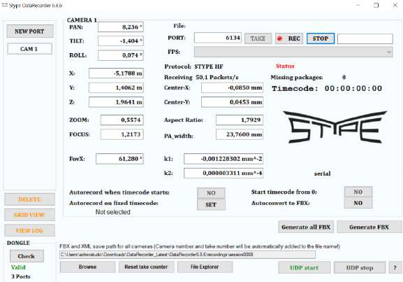
**Data Recorder**(数据记录器)是一款简单直接的工具,用于监控并记录正在发往渲染引擎的追踪数据。它还能检查丢包,因此在排查与设置相关的网络问题时非常便利。追踪数据被保存为 .xml 文件,应用之后可将其转换为 .fbx。免费版把记录时长限制在十秒,并把可记录的端口数限制为仅一个。
**RedSpy Control Center**(RedSpy 控制中心)是一个基于浏览器的平台,用于通过网络监管和控制任意数量的不同 RedSpy 系统。大多数核心 RedSpy 功能的控制都内置在控制中心界面里,而对系统的完全控制则可通过 VNC 访问轻松实现。配置文件现在集中存储,而不再分散在各个单元上,这使得不同相机设备与不同主机之间可以方便地混搭。这给你的工作流带来一层灵活性:由于一套系统只需一键就能配置好、随时可投入生产,相机设备可以轻松地在不同影棚之间转移。
# Contents
- Introduction
- Parts List
- Get Familiar with the Camera
- Get Familiar with the RS Main Unit
- Optional RedSpy Add-ons
- Wizard: Step-by-Step Setup
- 1 Placing the Markers
- 2 Mapping
- 3 Map Calibration
- 4 Define Virtual Studio
- 5 Mounting the RedSpy Camera
- 6 Setting up IP Addresses
- 7 Fine Tuning
- RedSpy User Interface Overview
- Home Screen
- Network
- Offsets from Main Camera
- Mapping
- Sliders
- Lens Calibration
- Profiles
- License
- Diagnostics
- Run the RedSpy Setup Wizard
- Complementary stYpe Products
# Introduction
RedSpy is an optical camera-tracking solution combining incredible accuracy with the resilience to handle suboptimal operating environments typical of the real-world production setting. Retroreflective markers are placed around the studio with the RedSpy camera capturing their position. Image-based information is then supplemented by the IMU data and interpreted by finely tuned, intelligent algorithms designed to deliver the highest level of camera tracking quality. This enables the RedSpy to deal with even the most elaborate of camera movements, making it suitable for anything from cranes and Steadicams to handheld rigs, without ever compromising your creative freedom.
The user interface includes a built-in, step-by-step installation wizard guiding the user in completing the initial system setup. Appropriate instructions are communicated at each and every stage along the way — simply following along with them will be sufficient in achieving reliable camera tracking performance. Nonetheless, a complementary manual is provided with the goal of offering additional insight into RedSpy's inner workings. For a first-time installation, using the wizard will ensure a smoother setup experience, even for studios familiar with the nuances of camera tracking. When working with a system that has already been set up, refer to the overview of the different interface tabs in the User Interface Overview section.
# Parts List
A complete RS kit ships with the components listed below. Your kit may include a slightly different set of parts than those listed here.


1. RS Camera
2. Main Unit
3. 7" HDMI Touch Screen Monitor
4. RS Power Supply
5. Mains Power Cable
6. RS Power Cable
7. RS External Encoders
8. RS Canon Lens Cable
9. RS Fujinon Lens Cable
10. Ethernet Cat6 Cable 20m
11. HDMI Touch Screen Cable
12. High Resolution Lens Encoder Extension Cable 0.4m
13. Universal Camera Mount
14. VF Nato Magic Mount
15. RS Extension Bar Mount
16. Universal Lens Bracket
17. External encoder mount D15 set
18. Ext. Encoder Rod Mount 15mm, 19mm
19. Extension bar Rods Mount 15mm, 19mm
20. PTR angle adjustments add-on for VF Nato mount
21. Canon Gears 60T
22. Fujinon Gears 50T
23. Cine Gears 38T
24. Flexible Adjustable Lens Gear Rings
25. Metric + Imperial sets of Allen/Hex keys
26. Cables, tools and small accessories bags
27. Digital Leveler
28. stYpe USB Dongle
29. Wifi USB stick
# Get Familiar with the Camera

- **RS marks** — the RedSpy logo and version number located on the front of the camera.

- **Indicator LED** — illuminates on every button press. It also lights up in blue when the system first starts up, confirming that the camera is receiving power.
- **CAM Port** — RJ45 port connecting the RedSpy camera to the system's Main Unit, enabling their communication and powering the camera via PoE.
- **Action Button** — contextual button executing different functions depending on your position inside the RedSpy user interface.
- **Lens Encoders Port** — either the external encoder set or the Fujinon/Canon lens cable connects here, providing the system with lens position data.
> **Suitable PoE standards and appropriate cabling**
>
> The RedSpy camera doesn't have to plug into the Main Unit directly — it will work with both 802.3at (PoE+) and 802.3bt (PoE++) compliant PSE (Power Sourcing Equipment) devices. This PSE device will conventionally be either a network switch or a PoE injector. Twenty-meter-long Cat 6 UTP cable is supplied as part of the kit; however, Cat 7 cables are recommended if the distance between the RedSpy camera and the Main Unit is greater still.
# Get Familiar with the RS Main Unit

- **Power** — On/Off button located on the front of the Main Unit.

1. **EXT LAN** — RJ45 port delivering the tracking data, either directly or via a network switch, to the rendering workstation.
2. **USB** — two USB-A ports for connecting peripherals such as mice, keyboards, touch screens, Wi-Fi adapters and flash drives.
3. **IPMI** — system monitoring and remote control RJ45 port.
4. **RS CAM** — RJ45 port connecting the Main Unit to the RedSpy camera, enabling their communication and powering the camera via PoE.
5. **PWR1** — main power supply port.
6. **PWR2** — redundant power supply port.
7. **Video output** — options include an HDMI port and a DVI port.
8. **LTC** — BNC port for the time code generator.
9. **SYNC** — BNC port for the sync generator.
# Optional RedSpy Add-ons

The **RedSpy Cine Expansion Module** makes it possible to utilize Cooke /i Technology or Zeiss eXtended Data protocols and read both lens and distortion data directly from the lens itself. The RedSpy camera slots on top of the module and interfaces with a suite of additional ports on the back of the device.

**Watcher X** is a markerless tracking add-on which enables the RedSpy system to reliably track the camera even when the marker map is completely occluded or otherwise out of sight. On set, it allows the camera rig to seamlessly move in and out of tight spaces, such as vehicle interiors, or directly beneath various set pieces without compromising the tracking quality. When shooting on location, its sensors can map out the physical environment and therefore remove the need for retroreflective markers altogether. Assuming that the RedSpy system has already been configured, setting up Watcher X is as easy as mapping the area by dollying the camera rig around and then capturing four reference positions in order to align the resulting map with the primary marker map.
# Wizard: Step-by-Step Setup
## 1 Placing the Markers
Although alternative approaches are possible, two conventional ways of installing the retroreflective markers would see them placed either on the ceiling (preferred) or on the floor. Choose the method you consider the most fitting for your particular circumstances. In both scenarios, marker size and the recommended distance between individual markers will be determined by the average distance from the RedSpy camera to the marker grid itself. Naturally, the total marker amount will also depend on the size of the area for which camera tracking is being implemented. If you are unsure about the amount of markers you are using, err on the side of there being too few, and spread too far apart, rather than the opposite. A marker grid density that is too high will have a more pronounced detrimental effect on tracking quality than one that is slightly too low.
> **Adhere to the following rules when installing the markers:**
>
> - Markers must be placed on a flat surface.
> - Markers must be arranged in an irregular fashion, making an effort to avoid repeating patterns as much as possible.
> - A range of permissible distances between individual markers must be maintained throughout the marker grid.

## 2 Mapping
Mapping the marker grid will give the RedSpy an opportunity to register and memorize individual marker positions, thereby turning them into detections based on which it will recognize its location on set later on.
### LED Brightness & Detection Threshold
The tracking reticle is what sets retroreflective markers apart from chance environmental reflections. It signifies that a particular reflection has been interpreted as a marker, while the diameter of the grayish circle within gives an idea of the reflection's intensity. When mapping a new area, the reticle will initially be highlighted in red. As you go along, and the system proceeds to memorize the map layout, the color of the reticle will gradually change depending on the robustness of a particular detection. Eventually, all markers should present with a teal reticle around them.

Ahead of mapping the studio, it's essential to dial in the IR LED `BRIGHTNESS` and detection `THRESHOLD` to appropriate levels. The more distant the RedSpy camera is from the marker grid, the higher the LED brightness needs to be in order to produce reliable detections. Increasing the detection threshold helps eliminate weak, irregular reflections stemming from studs, screw heads or different metal componentry protruding from the studio ceiling. Decreasing it, conversely, will enable the RedSpy to rely on less visible markers for tracking, add to the overall number of detections in its field of view, but also lead to an increase in processing load.
Both sliders should be adjusted within a moderate range, avoiding extreme values for best results. A good rule of thumb is to set them so as to allow a degree of empty space between the marker reflection and its reticle. Taking the IR LED `BRIGHTNESS` level too far will lead to tracking reticles eventually disappearing from markers altogether — rendering them useless for tracking purposes. Likewise, lowering the `THRESHOLD` value excessively will extend detections to various non-marker objects in the environment and consequently compromise the tracking.
Gray ellipsoid shapes present a clear indication of reflective noise in the RedSpy's FOV. Limiting obstructions directly in the tracking camera's line of sight, such as the jib head, will go a long way in preventing them. Alternatively, try mitigating their obtrusiveness by adjusting the two aforementioned parameters.

### Mapping Process
Mapping should start from the center of the studio space, either holding the RedSpy camera firmly in hand or with it already mounted to the camera rig. It's advisable to keep it orthogonal to the ceiling surface, with the orientation around its axis of symmetry and its height from the studio floor both remaining consistent throughout. During the initial mapping phase, movements should be slow and deliberate, being mindful not to occlude the markers from the camera's perspective with your hands, head or loose-fitting clothing. Once the initializing phase is through, RedSpy will accommodate quicker movements. Follow the visual cues in the interface as you go along; red, orange and yellow reticles indicate markers whose exact position is yet to be determined. Once the reticle turns teal, its position in the marker grid is fully defined.
Best practice would see the RedSpy operator moving from and returning to the same origin point in the middle of the set, iteratively and gradually chipping away at the parts of the marker grid that are yet to be memorized. Red reticle markers should cover no more than 1/3 of the camera's FOV at any one time. Once the mapping process is complete, choose `STOP EXPANDING` and save the map. Switching over to the `TRACK` view enables you to inspect the quality of the map by moving around the set. Rogue detections can be recognized by excessively long marker tails appearing when the RedSpy camera is in motion. Any such markers can and should be deleted from the map.
> **Gyro calibration on start-up**
>
> On every Main Unit start-up it's necessary to allow the RedSpy camera enough time to calibrate its gyroscopic sensor. If still not mounted to the camera rig, keep it resting on a firm, flat surface as long as the red notice icon is flashing. Once the flashing subsides and the icon disappears, it's possible to resume mapping the studio.
## 3 Map Calibration
### Floor Align
Starting with `FLOOR ALIGN`, map calibration will allow the system to contextualize the marker grid within real studio space. Continue by placing the RedSpy camera across three different positions (at a minimum), spanning as much of the set as possible, pressing the `+` button once you're ready to make a capture. Make sure that its distance from the ceiling remains exactly the same for every capture point — this being easiest to achieve by resting it directly on the floor itself. For floor-installed markers, consistent height across different capture points can be obtained by relying on anything from a tripod or a dolly to a C-stand. As before, keep the RedSpy camera perpendicular to the marker surface while capturing positions.
> **Using the Action Button**
>
> Instead of interacting with the UI, select individual capture points via the Action Button on the side of the RedSpy camera. The indicator LED will light up with every button press. Once satisfied with the number of captured positions, exit the `FLOOR ALIGN` menu by long-pressing the Action Button for 3 seconds.
### Set Scale
The scale of the marker map is defined by the measured distance between two discrete capture points. These positions should be as far apart as possible while still staying within the confines of the marker grid. A rectangular floor plan would see them located at opposing ends of an imaginary diagonal cutting across the area. Mark the first position by placing an item against the RedSpy camera body, as a reference. Then, with the camera moved onto the second position, a laser distance meter is used to measure from the reference item to the camera. Make an effort to keep the RedSpy's orientation around its axis of symmetry consistent across both capture points.
## 4 Define Virtual Studio (Setting the Zero Point)
### Setting the Zero Point and Zero Pan
`ZERO POINT` represents a position in physical space corresponding to the origin point of the virtual scene.
`ZERO PAN`, on the other hand, lays down a line coinciding with the rendering engine's default forward axis.
Set down the RedSpy camera at an appropriate spot in relation to which the visual artists have crafted their scene, and confirm your choice either by choosing the `>` button or with a press of the Action Button. Then, keeping the RedSpy camera orientation consistent once again, reposition it as far as possible along a desired path to complete a line segment — thus finalizing the position of the tracking coordinate system relative to the surrounding environment.
## 5 Mounting the RedSpy Camera
An accurately defined spatial relationship between the RedSpy's CMOS and the studio camera sensor is a key requirement in the pursuit of pin-sharp tracking precision. Firmly attach the RedSpy to the camera rig using one of the supplied mounting brackets. Then, depending on the mounting position you've chosen, select the direction in which its network cable is pointing. Proceed by measuring the first translational offset from the studio camera optical axis to the top edge of the RedSpy's casing (1). The second offset determines how far off to the side the RedSpy is positioned on a transverse axis (2), while the third one gauges the distance from the studio camera focal plane to the RedSpy's axis of symmetry (3). Carefully measure the distances, keeping in line with the UI cues.

## 6 Setting up IP Addresses
### Set Source IP Address
Default settings assume that the RedSpy Main Unit and the rendering workstations it's delivering tracking data to are located on the same subnet, with a CIDR of /24 — implying a 255.255.255.0 subnet mask. If instead the workstations are assigned to a different, separate network, `Gateway IP` can be leveraged to access them. It's also possible for the Main Unit to lease an address from a DHCP server configured for that purpose. Move forward by either inputting the desired static IP under `Source IP` or enabling the `DHCP` checkbox.
### Set Destination IP Addresses
A different tracking protocol can be used for each and every destination device, while the tracking delay adjustments are applied universally. Both can be configured by selecting `EDIT` right beside the destination IP address. Be wary not to assign a port that's already in use by another network process on the rendering workstation. When finished, use the ping button to ping the destination device and perform a network connectivity check.
## 7 Fine Tuning
With all of the foundational RedSpy systems now in check, we're ready to fine-tune the tracking behavior by relying on a simple calibration scene. The wizard offers two distinct fine-tuning procedures based on whether the studio camera is movable or fixed in place. Although the choice must be made at the very outset, the initial steps are the same across both scenarios. The manual will therefore make the distinction between the two later on.
Select your camera from the list and pick the resolution that's being used. Depending on the resolution it's been set to, the camera will scan only a portion of its sensor with every recorded frame. Knowing this effective width of the imaging sensor is paramount to seamlessly using your lens files across different types of cameras. Moreover, successfully utilizing stYpe's extensive lens file repository will also rely on being familiar with the sensor's measurements. For a number of established camera brands, the effective sensor width will be determined automatically once you input the model and recording mode. If your camera is not listed, consult its user manual and enter the sensor width manually.
A considerable amount of baseline lens files for conventionally employed broadcast lenses is included with every RedSpy build. It's possible to either build upon these or create a new one entirely from scratch by selecting the `Default` preset. If there are no baseline lens files for the lens of your choice, pick the one offering the most similar range of focal lengths. Previously created or imported lens files can be accessed through the `MY LENSES` menu.
> **Baseline lens files — managing expectations**
>
> Two lenses of the same make and model can greatly differ in their distortion profile. Even though an exact fit is possible, adjustments are usually necessary to make the most of the baseline file.
### Lens Ranges
Choose between using internal or external encoders. For internal encoders, connect the included Canon or Fujinon Lens Cable into the Virtual or EXT port respectively to tap into the lens data stream. The LEMO connector on the other end of the cable will slot into the lens data port on the RedSpy camera. With the optional Cine Expansion Module it's also possible to utilize Cooke /i Technology or Zeiss eXtended Data protocols and read both lens and distortion data directly from the lens itself, without relying on an external lens file.
When using external encoders it's necessary to ensure their gears reliably mesh with the lens gear rings. Each encoder has a spring-loaded base plate with two through-holes, one of which will slide onto the encoder mounting shaft, which is in turn secured by the lens bracket. Orientation of individual encoders can vary depending on the space constraints; however, the through-hole that's sitting on the mounting shaft should universally be the one that's farther away from the lens centerline. In this way the spring tension will be leveraged towards keeping the gears engaged. Scan the QR code below to access the encoder mounting video tutorial. Once installed, assign which encoder in the daisy chain is tracking zoom and take them through their entire range of motion. This will be a necessity on every system restart. With lenses incorporating no hard stops the calibration procedure is not necessarily self-explanatory; rotate the focus ring to reach the minimum focusing distance while being careful not to overshoot. Confirm this position in the UI. Next, rotate it to reach infinity focus and then for an additional quarter of a turn before proceeding.


### Preparing the Scene
Creating a calibration scene in the rendering engine of your choice is as simple as inserting a cone mesh into your level upside-down and placing it so that its tip sits precisely in the world origin (0,0,0). One of the remaining tracking markers will be applied onto a wall opposing the studio camera, approximately at the imaging sensor's height while the camera is level. Throughout the next couple of steps you will be adjusting a number of tracking parameters based on the cues from the rendering engine.
With the camera at a reasonable distance from the wall, zoom in all the way. Adjust pan and tilt so as to square up the viewfinder crosshair with the marker. Measure the distance from the camera's sensor to the wall. The RedSpy will now temporarily readjust its zero point and place it in the center of the tracking marker. Once the fine-tuning is done, it will automatically revert back to the point we've designated during the `Define Virtual Studio` phase. Referring to the rendering engine viewport, the sharp tip of the AR cone should now sit in the marker center.
### Adjust Lens Center
`Center Shift` will accommodate vertical and lateral shift in the frame across different focal lengths. It'll be necessary to redo the adjustment every time a new lens is swapped onto the camera body — with some lens mounts offering a more consistent lens-to-sensor alignment than others (PL as opposed to EF, for example). Provided that the camera is still zoomed all the way in, zoom out until reaching the widest possible shot. Observe how the cone is no longer positioned in the very center of the marker. Using the `Left-Right Offset` and `Up-Down Offset` sliders, adjust the center shift value and realign the cone with the marker center. Zoom in on the marker once again. This time the same set of sliders is used to precisely readjust the position of the temporary zero point. Once the cone is back in the marker center, zoom out and iterate through the described steps until the cone's tip is perfectly centered irrespective of the zoom level. Skip this section entirely if using a prime lens.
> **Global vs. local center shift**
>
> With some lenses the cone might sit perfectly aligned with the marker center at both ends of the focal length range, yet still meander about when employing various other zoom levels. This can be compensated for later on during the `EDITING LENS TABLE` phase by assigning different center shift values for different zoom levels, as opposed to applying just a singular, global adjustment.
Now it's time to subtly adjust the RedSpy's rotational offsets, since it's unlikely that the default values for `TILT`, `PAN` and `ROLL` (90, 0 and -180 degrees respectively) are an exact match for the tracking camera's actual position.
#### Fine Tuning Tracking [Pan — Edges]
Zoom all the way out and pan the camera side to side. Examine if the tip of the cone describes a sloping path across the screen. If so, adjust the `Up-Down Offset` until the path described by the cone resembles a parabola opening downward, with its vertex sitting directly in the middle of the marker — i.e., until the tip of the cone remains at an equal vertical offset from the marker center at either edge of the shot. At this stage our lens file likely leaves much to be desired, so it's not expected for the cone to track horizontally with the marker across the screen. For now, focus solely on its vertical movement.

Here the setup procedure diverges depending on whether we've selected Movable or Fixed / Semifixed camera movement at the section's start.
### 7A Movable
#### Fine Tuning Tracking [Moving the Camera]
Fully zoom in on the marker and dolly forwards until the UI shows the camera in the near marker position. Using the sliders, readjust the cone's position so that it sits in the marker center. Then, dolly the camera away from the marker to reach the far position, readjusting the sliders if necessary. Once again, iterate through these two steps until the cone sits flush with the marker along the entirety of the dolly path.
### 7B Fixed / Semifixed
#### Fine Tuning Tracking [Pan — Center]
Static camera fine-tuning is a less involved process, but certain steps still need to be taken to make the most of the tracking system's capabilities. Stick with a wide-angle shot through the entirety of this section. Continue panning from left to right and use the `Up-Down Offset` to now flatten the parabola described in the previous step. Adjusting the slider will cause the cone to lose its position in the marker center. Proceed once the cone remains at an identical vertical distance from the imaginary horizontal across a range of different pan angles.

#### Fine Tuning Tracking [Tilt]
Tilt the camera all the way up, then all the way down, until the tip of the cone reaches the very edges of the frame. Observe how the cone's tip is not moving along a perfectly straight vertical line. Rather, it's describing a curve which now resembles a horizontal parabola. Adjust the `Left-Right Offset` until the cone's horizontal position remains stable irrespective of the tilt angle.
With the rotational offsets adjusted, all that remains is to set up the lens and focus distance tables. These last two sections apply to all setups, regardless of whether the camera is movable or not.
### Editing Focus Distance
Setting up the focus distance table will enable an accurate degree of sharpness of the AR graphics based on their position in reference to the virtual camera and the current focusing distance, thereby mimicking the sharpness levels of the surrounding physical environment.
It's possible to either manually measure the distance between the camera's focal plane and the reference object as it's moved farther and farther away, or to simply enter the values as indicated by the focus distance markings engraved on the lens itself. For this latter approach it's necessary for the camera to be properly shimmed, i.e. for the lens to be back-focused beforehand.
When proceeding with the `MANUAL FOCUS DISTANCE MEASUREMENT`, zoom all the way in and adjust the lens to its minimum focusing distance. Bring the reference object right against the camera, until it comes into focus. Make the first measurement, choose `Edit 0 Focus` and input the measured value. Then, move the reference object some ways farther from the camera and bring it back into focus. Select `+ ADD DOF POINT`, measure and input the distance. Repeat these steps for up to 8 different focusing distances, not including the infinity focus. Concentrate more of the measured points towards the tail end of the focusing range, as this is where the change in the focusing distance for a given adjustment of the focus ring ramps up quite quickly.

### Editing Lens Table
It was already mentioned that each lens has its own unique distortion signature. The rendering engine then must take these distortions into consideration when mapping the scene onto the screen space. It has to reliably contort the AR graphics in accordance with the lens perspective so as to not break the immersiveness of the composited visuals. In doing this, it will rely on data points collected during the lens calibration process.
All throughout the setup it was apparent that the cone loses its bearing in physical space every time the camera assumes too large of a pan angle. Calibrating the lens file by adjusting the `FOV` slider will lead to the cone preserving its position irrespective of the camera movements that are being employed.
Start with the lens adjusted to its shortest focal length and work your way towards full zoom. Pan to one side so as to position the tracking marker one third of the way towards the edge of the frame. Adjust the `FOV` value until the cone realigns with its original position. Pan a bit farther still, with the marker now two thirds of the way to the frame border. Readjust `FOV` until the cone once again realigns with the marker. Finally, pan all the way so as to place the marker right against the outline of the image and repeat the adjustment. Then, pan the camera to the other side and refine the `FOV` value if needed. Continue on to the next zoom level once the cone sits still in the marker center regardless of the studio camera pan angle.
> **Splitting the difference**
>
> It's possible that an `FOV` value which is exactly right when panning left won't produce as satisfying a result when panning right. In such cases, split the difference between the two positions, thereby reducing the total degree of graphics drift.
With the setup phase now complete, pick a profile name and save it. Password-protecting the profile will prevent it from being accidentally deleted. Multiple profiles allow for quick and efficient operation across different studios and when using a number of different studio cameras.
# RedSpy User Interface Overview
## Home Screen

1. Switch between the home screen and the RedSpy tab interface.
2. Access the tracking data overview across different destination devices. Triple-click on the `Protocol` field to cycle between FreeD or StypeHF tracking data. The readout will show either LOCALIZING or EXPANDING depending on how the toggle switch (9) on the right-hand side is set. The health bar just below communicates the quality of our marker map.
3. Press and hold to customize the status list. Pick and choose among the following options:
- **GENLOCK** — inspect the current system frame rate. The check mark confirms that the reference signal is coming in. In the absence of a sync generator, the RedSpy will default to 55 frames per second.
- **GYRO** — every time the RedSpy system is powered on, the camera's gyroscopic sensors will go through a calibration procedure. Keep the studio camera still for as long as the red notice icon is visible. Once the calibration is completed, a check mark will be shown instead.
- **LENS RANGES** — if the focus and zoom values are highlighted in red, encoder ranges are yet to be set. To do so, take both the focus and zoom rings through their entire range of motion. This will be a necessity on every system restart.
- **WARNINGS** — shows active system warnings.
- **LTC** — timecode readout.
- **Record** — trigger the built-in tracking data recorder. The resulting .xml files will be saved inside the Recording folder, inside the RS3MainServer directory.
- **RED** — enable the RED camera control UI.
- **THRESHOLD** — adjust the detection `THRESHOLD` level right from the home screen, with a clear view of the markers.
- **MASKING** — masking out reflections or markers with particularly long tails can lessen the reprojection error in a specific position on the set. Regular masks will be sufficient for static shots, while with a dynamic mask it's possible to retain an otherwise unobstructed view of the map and block out a particular surface only once the studio camera assumes an aggressive enough tilt angle.
- **WATCHER X** — to map the area, hit `RESTART` under the `GENERAL` tab and then slowly move the camera rig around. The `Map Match` value communicates the precision with which Watcher X currently perceives its immediate surroundings, whereas `Scene Detail` reports if there is sufficient information in the images it is capturing. Select `SAVE` when both of these metrics remain consistently around the 100% mark all throughout the area. Finally, align the Watcher X map with the baseline marker map by selecting either `MANUAL ALIGN` or `AUTO ALIGN` under the `SETUP` tab. Toggle the `DATA TYPE` between `REDSPY`, `WATCHER X` or `COMBINED` depending on the blend of tracking data you'd like to use for a particular scene.
4. Toggle the RedSpy icon in the bottom left corner in order to access the RedSpy toolbar. Here it's possible to quickly change between different lens files, load any of the saved profiles or restart the Main Unit.
5. Switch between the `MAP` and `TRACK` views. Toggle `RAW`, then click and drag in order to overlay the marker grid on the RedSpy clean camera feed. This is especially useful when trying to pinpoint the exact source of a troublesome reflection.
6. Currently selected profile. If any changes are made, the system will prompt the user to save those to a new profile.
7. Turn the RedSpy camera on or off.
8. Start and stop the camera tracking.
9. Toggle between localizing and expanding modes; use the expanding mode to add additional detections to the current map.
10. Press and hold to lock the screen and prevent accidental changes to any of the settings.
## Network
Conventionally, both the Main Unit and the destination devices, i.e. rendering workstations, are located on the same, shared subnet and employ static IP addresses. Use the `Source IP` text box to define the Main Unit's IP address. Then, choose the desired subnet mask by entering the appropriate CIDR number under `Subnet`.
It's also possible to have a DHCP server lease an IP address to both the Main Unit and the surrounding network devices. In this case the setup is as easy as enabling the `DHCP` checkbox in the upper right corner of the interface.
The ping button performs a network connectivity check by pinging a specific destination address, while the remove button removes a particular address from the list. Addresses outside the defined subnet, as well as destinations that have been listed two or more times by accident, will be highlighted in red.
## Offsets from Main Camera

Rotational and translational offsets are utilized to accurately define the position of the RedSpy camera in respect to the studio camera imaging sensor.
Starting RedSpy orientation with `PAN`, `TILT` and `ROLL` set to 0° describes a position in which its RJ45 port is pointing directly downward to the floor, with the LED ring facing the same direction as the studio camera lens. The most frequently employed installation position will see the RS looking towards the ceiling with its ethernet cable extending towards the back of the camera rig. Assuming the default TPR rotation order, this will necessitate adjusting `TILT` to 90° and `ROLL` to -180°.
`X`, or left-right offset, is measured from the studio camera optical axis to the RedSpy's axis of symmetry. A positive offset implies that the RedSpy is positioned off center and to the right, as observed by the camera operator. If it's positioned off to the left, enter the measured value as a negative number. `Y`, or up-down offset, is measured from the top of the RedSpy's casing to the studio camera optical axis. Its value is negative when the RedSpy is mounted above the studio camera and positive when it's installed below it. `Z`, or front-back offset, is measured from RedSpy's axis of symmetry to the studio camera focal plane, usually marked on the side of the camera body. It's positive when the RS attaches to the studio camera ahead of the focal plane and negative when it's mounted behind it.
If unsure about the way in which any of the outlined measurements are supposed to be taken, or about the appropriate rotational offsets for your particular installation, select `WIZARD` to access the offsets visual guide.
> **Offsets fine-tuning**
>
> Every time the RedSpy camera is taken off the camera rig and then reinstalled, the imaging sensors will assume an ever so slightly different position in respect to each other. For this reason it's important to redo the fine-tuning procedures described in either section 7A or 7B on every such occasion.
## Mapping

The mapping tab comprises two individual columns; actions on the left are mandatory and must be tackled every time a new studio has been mapped. They complete the map calibration process and will allow the system to contextualize the marker grid within real studio space. Conversely, actions on the right are optional and should be considered only under a specific set of circumstances.
`ALIGN FLOOR` defines the marker grid alignment in reference to the floor plane. A minimum of 4 captures is required. Keep the RedSpy camera at an equal distance from the marker grid for all capture points and cover as much of the set as possible.
`SET SCALE` determines the size of the marker map, as perceived by the system, and matches it with the actual set size. Two capture points are chosen and a distance between them is measured. These positions should be as far apart as possible while still staying within the confines of the marker grid. Mark the first position by placing an item against the RedSpy camera casing. Then, with the camera moved onto the second position, a laser distance meter is used to measure from the reference item to the camera. Keep the RedSpy's orientation around its axis of symmetry consistent across both capture points.
`ZERO POINT` represents a position in physical space corresponding to the origin point of our virtual scene. Set down the RedSpy camera at an appropriate spot in relation to which the visual artists have crafted their scene and make a capture. If the RedSpy has already been installed onto the camera rig, instead of 0, enter the height difference between the studio camera optical axis and the surface on which the zero point should sit. In this way it's possible to readjust the zero point's position without having to remove the RS camera and therefore without compromising the rotational offsets.
`ZERO PAN` lays down a line in physical space coinciding with the virtual scene's default forward axis. Keeping the RedSpy camera orientation around its axis of symmetry consistent, place it at an initial point, then reposition it as far as possible along a desired path to complete a line segment.
> **Map quality assessment**
>
> By tackling map calibration steps in a specific sequence, it's possible to simultaneously inspect the quality of the map itself. With `ALIGN FLOOR` completed, mark the first `SET SCALE` position, reposition the camera and input the measured distance. Leaving the camera in this spot, set down the `ZERO POINT`, then choose `ZERO PAN`. Make the first capture, bring the RS back onto the starting position and complete the second capture. Head to the home screen and select LOCALIZING to access the tracking data overview. With the FreeD protocol enabled, inspect the positional data that's being output. Assuming a perfectly flat studio floor, both X and Y should read zero with the Z value matching the distance measured during the set scale step.
`OPTIMIZE MAP` supplements the existing map information by adding various types of keyframes or by manually assigning a number of tracking markers to one and the same plane. Each keyframe will capture both a snapshot of the marker grid and record the concurrent position of the RedSpy camera. Feeding the optimization algorithm this data will result in marker position refinement throughout the entire map.
We differentiate between regular and plane keyframes. Regular keyframes are collected either manually or automatically by simply moving around the studio while the system decides when to make a particular capture. Plane keyframes, on the other hand, must be added manually, with the operator making sure to keep the RedSpy camera at exactly the same distance from the marker grid for every individual snapshot. Once an assortment of keyframes has been collected, select `Optimize` to trigger the optimization process. It's advised to first refine the map by relying solely on regular keyframes. Proceed with adding plane keyframes or selecting plane markers only if the first optimization cycle fails to yield satisfactory results.
As keyframes are being added, markers will be highlighted in a different color based on how many times they have been captured across different snapshots:
- **Blue** — marker is yet to be captured.
- **Red** — marker has been captured no more than two times.
- **Yellow** — marker has been captured either three or four times.
- **Green** — marker has been captured across 5 or more snapshots.
This provides useful feedback, as there's not much utility in collecting a completely different set of markers with every new snapshot. An overlap has to exist for the optimization algorithm to be able to achieve the desired results.
Criteria set for automated keyframe collection can be redefined by inputting two reference keyframes via the settings menu. These reference keyframes should be captured at a distance no greater than twice the distance between the RedSpy camera and the marker grid. The `Reset` button readjusts the criteria back to their default state.
Toggle to `Markers` to add plane markers. Select no more than 5% of the total number of markers that you're certain all lie in the same plane. For as long as the optimization is running, the `Optimize` button will read Stop instead. Once the button reverts back to normal, the map refinement process is complete.
`ROTATE MAP` allows for a precise adjustment of the `ZERO POINT` and makes it possible to achieve perfect alignment between AR graphics and real set pieces. This feature is of special importance when working with multiple RedSpy systems all in the same studio. As opposed to earlier RedSpy builds, once an adjustment is made, it immediately overwrites the existing alignment data while all six input fields reset to 0. Each consecutive change will be made in reference to the current virtual space alignment, as defined by the previous set of adjustments.
`LOAD ZERO POINT` applies a zero point previously defined inside a different profile onto the current one.
## Sliders
`Translational Smoothing` is used to iron out the graphics jitter that might occur while traversing a particularly rough spot around the marker map. The jitter will often be more apparent while shooting with a longer focal length, which is why it's possible to adjust the smoothing level for telephoto and wide-angle shots separately. Under most circumstances, it's best kept at its default value.
RedSpy cross-references its supposed position based on the tracking marker constellation with the IMU data at all times. By adjusting `Gyro Influence`, it's possible to sway this relationship one way or the other. Raising it will increase the system's susceptibility to gyro drift while also boosting its resilience to aberrations in the marker map. Best kept at its default value.
`Led Brightness` and `Detection Threshold` — the more distant the RedSpy camera is from the marker grid, the higher the LED brightness needs to be in order to produce reliable detections. Increasing the detection threshold helps eliminate irregular reflections stemming from various metal components protruding from the studio ceiling. Decreasing it, conversely, enables the RedSpy to rely on less visible markers for tracking, adds to the overall number of detections in its field of view, but also increases the processing overhead. Both sliders should be adjusted within a moderate range, avoiding extreme values for best results. A good rule of thumb is to set them so as to allow a degree of empty space between the marker reflection and its tracking reticle.
> **Active markers**
>
> Systems configured to work with active markers projected on an LED volume will present the user with two additional settings. `Exposure` does exactly what the name implies — it defines the RedSpy camera shutter speed and should be adjusted based on the ambient light level and the LED volume brightness. `Led Duration` introduces a phase offset into the RS's frame pacing which is leveraged so as to sync the RedSpy frame capture precisely with the interleaved frames displaying the marker grid. This becomes relevant when frame remapping, or an equivalent technology, is being used.
`Tracking Data Delay (Frames)` brings the tracking data in sync with the camera feed in environments where the latency in the video signal flow is larger than that of the network. Gauge the relationship between the network and video delay by panning the camera around and observing the behavior of the AR elements. Graphics appearing to readjust their screen-space position ahead of any camera movement is a telltale sign of the tracking data frames reaching the rendering engine before the video signal. Alternatively, if the tracking data lags behind the video feed, some video delay must be introduced on the rendering engine's side while keeping the tracking data delay slider at its minimum value.
`Data Sampling Sub-Frame Delay` enables further fine-tuning of the tracking delay, adjustable in 5% increments of the total frame time. It is relevant only once the `PTS` checkbox has been enabled. It adjusts the sync unit's buffering in order to correctly time the outgoing tracking frames, thereby reducing the system's reliance on extrapolated frames as much as possible.
`Data Rate` setting will allow the RedSpy frame rate to match the studio camera frame rate in scenarios where the sync generator operates either at a multiple or a factor of the project frame rate. This feature frequently comes into play when shooting slow-motion footage.
Tracked camera position is constantly being offset by the nodal distance, as defined by the lens file, in order to produce lifelike parallax error of the rendered graphics. `Ignore nodal DOF` instructs the system to stop adjusting the focusing distance by the said nodal distance. Unless your specific workflow demands otherwise, this option should be left unchecked, as it will disrupt the AR graphics from coming in and out of focus in unison with the real-world surroundings.
`Jumbo` checkbox should be enabled as long as the network interface that relays information between the RedSpy camera and the corresponding Main Unit can support frames that are over 1500 bytes in size. Configure the MTU setting on your network switch accordingly. Intermittent flashing of the entire map interface is a clear indication of dropped frames due to an MTU bottleneck.
Enabling `PTS` (packet timing stabilization) will cause tracking data to be sent from the RS CAM port on the Main Unit, instead of the EXT LAN port. In this case both the RedSpy camera, the Main Unit and the destination device plug into and communicate through the same PoE switch. Using PTS increases the overall tracking delay, but also ensures that the tracking data is delivered with a more uniform frame time.
## Lens Calibration

If `Auto Start` is enabled, the system will begin tracking the camera as soon as it's powered on. Depending on the way external encoders are mounted, it's sometimes necessary to invert their polarity so as to align the actual lens ring position with the appropriate encoder read-out. Normalized, the percentage read-out should show 100% for focus with the lens adjusted to infinity focus and 100% for zoom with the lens adjusted to its maximum focal length.
By default, the system will assume that the outermost encoder (encoder 2) tracks focus while the innermost (encoder 1) tracks zoom. Select `ENCODERS` to rearrange the individual encoder positions in the daisy chain.
Enable `DEPTH OF FIELD` to output the focus value as a focusing distance, or disable it to produce a normalized focus reading between 0 and 1.
Via the `LENS` menu you can either load a different lens file, make adjustments to the current one or set up an entirely new file based on one of the included baseline files. Each and every lens file comprises four distinct components which together allow the rendering engine to accurately and reliably distort the AR graphics, aligning them with the lens perspective:
- **`ADJUST CENTER SHIFT`** — every time a lens is attached onto the camera body it assumes a slightly different position in respect to the imaging sensor. That is to say, the center of the lens never truly coincides with the center of the sensor. Due to this minute misalignment, zooming in will result in a subtly different framing of the shot compared to when the lens was last swapped onto the camera. Center shift accommodates for this and ensures that the graphics remain firmly anchored in place irrespective of the zoom level. While the lens table and the focus distance table are adjusted on a "set it and forget it" basis, center shift needs to be redone each time a lens is reinstalled onto the camera.
> **Adjusting center shift**
>
> Start by enabling the center shift marker overlay in the rendering engine, then:
>
> 1. Zoom all the way in and align the marker with a reference object of your choice.
> 2. Zoom out to achieve the widest shot possible and observe how the center shift marker creeps away from the reference point.
> 3. Using the sliders, bring the marker back in line with the chosen reference.
> 4. Zoom all the way in and readjust the shot by panning and tilting the camera so as to get the center shift marker on top of the reference point once again.
>
> Keep repeating steps two through four and refining the center shift value until the center shift marker sits firmly in place regardless of the zoom level. If the center shift marker keeps drifting away from its reference around the middle of the focal length range, even though it's in position for the close-up and wide-angle shot, the lens might demand unique center shift values across various zoom levels instead of a single, global adjustment. This can be adjusted in the `EDIT LENS TABLE` menu.
- **`LENS TABLE`** — each lens has its own unique distortion signature. The rendering engine must take these distortions into consideration when mapping the scene onto the screen space. Overlay some graphics on a reference object so as to serve as a guide in making adjustments to the `FOV` value. Pan the camera around and notice how the graphics drift away from the object they're supposed to be anchored to as the pan angle increases. Use the `FOV` slider to realign the graphics, repeating the process for each of the zoom levels.
- **`FOCUS DISTANCE TABLE`** — have a reference item held up in front of the camera with the lens set to its minimum focusing distance. Zoom all the way in. With the reference item firmly in focus, measure its distance to the camera focal plane, select `Edit 0 Focus` and input the measured value. Reposition the reference object farther and farther away from the camera with every new measured point.
- **`SET SENSOR SIZE / CROP SENSOR`** — scale down a lens file which was initially calibrated using a camera employing a larger sensor.
## Profiles
Choose between loading, saving or exporting a profile. To prevent irreversibly compromising a broadcast-ready setup, RedSpy does not write changes to existing profiles. It instead demands that a separate profile is saved each time we'd like to introduce any changes to the current configuration. As an additional safeguard, profiles that we'd like to prevent from being accidentally deleted can be password protected.
## License
Check the current build version, license expiration date, Main Unit and RedSpy camera part numbers. This tab will be mostly used when working together with stYpe Remote Support Engineers while renewing the operating license or installing software updates.
## Diagnostics
The Diagnostics tab facilitates quick and efficient support in case of a system malfunction. Use it to provide stYpe Remote Support Engineers with access to the system.
## Run the RedSpy Setup Wizard
Launch the step-by-step setup wizard at any time to revisit the full installation procedure described earlier in this manual.
## Complementary stYpe Products
**TWIM LensCal** is a standalone Windows-based app that streamlines the process of configuring lens files for both broadcast and cinema lenses. It drastically cuts down on the amount of time needed for a complete calibration, requires little to no previous experience and simultaneously offers results unattainable to even the most seasoned on-site engineers relying on legacy calibration methods. Two calibration boards are positioned at a specific distance from the camera's focal plane. The operator then takes the camera through pan and tilt movements so as to align different on-screen targets with the calibration boards. The process is repeated for different focus and zoom levels until the lens distortion profile is completely mapped. The app then generates a lens file which is transferred over to the RedSpy Main Unit.
**Data Recorder** is a straightforward solution for monitoring and recording the tracking data that's being sent out to the rendering engine. It has the added capacity to check for packet loss, which makes it a convenient tool when troubleshooting any network-related issues with your setup. Tracking data is saved into an .xml file which the app can then later convert into an .fbx. The free version caps the recording length to ten seconds and limits the number of recorded ports to just one.


**RedSpy Control Center** is a browser-based platform used to supervise and control any number of different RedSpy systems over a network. Controls for most of the core RedSpy functionalities are baked into the Control Center UI, while total control over a system is easily exercised via VNC access. Profiles are now centrally stored, instead of being dispersed across individual units, which makes it easy to mix and match different camera rigs with different Main Units. This introduces a layer of flexibility into your workflow, with camera rigs easily moving between different studios, since a system can be configured and made production-ready at a touch of a button.
